
Eng. Puliatti Giovanni Trenitalia S.p.A.Italy
Eng. Maccaferri Stefano ALSTOM Transport S.p.A. Italy
Eng. Scatà Marcello ALSTOM Transport Telecommunication S.p.A. Italy
Versione PDF
Abstract
The aim of this article is to put in evidence Alstom and Italian Railway (Ferrovie dello Stato) experience with regard to the ERTMS/ETCS level 2 on Italian trial site, focusing on the train-borne aspects.
After an overview of the ERTMS train-borne subsystem, the different on-board Alstom peripherals installed for the tests campaign will be described. Then, the Italian trial site will be shown pointing out the problematic encountered during the installation of the on-board equipment and the functional tests performed, reporting also some experimental results.
Introduction
ERTMS (European Rail Traffic Management System) is the initiative from the EC to create a unique control command system for railways to enable interoperability throughout the European Rail Network.
On the Italian trail site, located on the DD line between Firenze and Arezzo, is under test the ERTMS/ETCS level 2, that consists in a continuous signalling radio system.
ERTMS/ETCS on-board Alstom solution
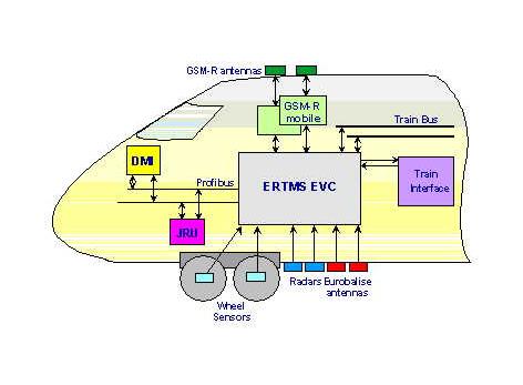
ERTMS/ETCS on-board Alstom solution is shown in Fig1.
Fig.1 : ERTMS/ETCS on-board Alstom solution
The EVC (European Vital Computer) is the central equipment of the on-board system. The EVC communicates with the Radio Block Centre (RBC) track-side equipment through the GSM-R network. Two GSM-R modules are necessary to ensure the handover when the train passes from a zone controlled by a RBC to another one. The EVC supervises the movement of the train and controls the information shown to the driver on the DMI (Driver Machine Interface). The on-board computer constantly calculates the train’s position through its own odometer based on radar sensors (duplicated for availability purposes) and wheel sensors (duplicated for safety reasons). The train position is calculated from Eurobalises on the track, acting as common references between the on-board and track-side ERTMS equipment. The Eurobalises detection is carried out through the Eurobalise antenna (duplicated for availability purposes).
When the situation demands, the EVC can apply the emergency brake in a fail safe way or can interact with the other train devices directly or via a train bus (duplicated for availability purposes).
All the juridical data necessary in case of accident are continuously stored in the JRU (Juridical Recorder Unit). As shown Fig.1, the JRU and the DMI are connected to the EVC by means of a Profibus line (duplicated for availability reasons).
Description of the peripherals installed for the test campaign
Hereafter, a description of the peripherals used for the test campaign and currently installed on the Italian test train (the ALe601-Le480) is given.
European Vital Computer (EVC)
The EVC is the train-borne cubicle which encloses all the electronic needed for the on-board processes’ management.
The main on-board functions are:
- calculation of the dynamic speed profile, taking into account the train running characteristics which are know on-board;
- comparison of the actual train speed with the permitted speed and application of the brakes if necessary;
- selection of the most restrictive value of the different speeds permitted at each location ahead;
- sending the information to be displayed to the driver;
- sending the train position relative to the balises detected to the RBC;
It performs the above-cited functions, on the basis of:
- the signalling information received from track mainly via the GSM-R;
- the train speed and train location computed by itself on the basis of the signals received from the odometric sensors and relative to track-side reference points;
- the information entered by the driver;
- data either stored by the EVC itself or received from an external device.
The EVC is the heart of the ERTMS/ETCS train-borne subsystem. It is therefore designed around a multi-processor based unit. The triplicated architecture (i.e. three processing channels), with a two-out-of-three redundancy, ensures the safety and provides fault tolerance to achieve the high availability which is required for this project.
The three processing channels of the EVC have the same hardware architecture and the same software programs and:
- receive the same input information;
- perform the same calculations in parallel;
- issue the same outputs to a two-out-of-three voter.
However, to ensure that the same calculations are performed in parallel (i.e. at the same time) by these three processing channels, a macro-synchronization procedure is performed beforehand. This is achieved through specific point-to-point serial links between the three channels.
The outputs generated by each channel are then voted by hardware (vote two-out-of-three), before being applied to the external elements.
A cross-check of the channels is performed continuously by the three channels. This allows to identify and to shut down any channel in case of detection of an incorrect operation or a component failure, by the remaining two healthy channels.
From a safety point of view, when a channel is shut down, the other two ones continue to operate normally in a two-out-of-two configuration, without any reduction in the level of safety.
From a mechanical point of view, the EVC is enclosed in a 84TE 6U rack and can house power supply module and boards 220mm long. Five power supply modules are foreseen: two 24V modules feeding the two Eurobalise antennas and three +5V/± 12V modules dedicated to the three independent channels.
The EVC power supply fulfils and meets the voltage range, the variations and the interruptions of the battery voltage input in accordance with the Railway applications EN50155 standard.
The design stage of the rack equipment is provided with integral shields for EMC/EMI problems. The shielding effectiveness and performance match the whole enclosure shielding objectives in compliance with the prEN50121-3-2 and EN50155 standards.
Driver Machine Interface (DMI)
The DMI represents the interface between the ERTMS/ETCS on-board equipment and the driver. This device has been developed by Alstom in accordance with the FIS specifications for MMI and prEN50XX6 Cenelec normative and has been designed to be used in the hardest environmental conditions. The main functions performed by this module are:
- to show, through a graphic display, all the information necessary to drive the train;
- to enter or modify the train data;
- to allow the driver to interact with the system (acknoledgement).
The mechanical dimensions of the DMI are (LxHxD) 300x250x108mm and its weight is approximately 8Kg. The display is a 10.4" TFT LCD with a resolution equal to 640x480 at 256 colours. A resistive touch-screen is available for data entry and acknowledgement procedures. The DMI is equipped with eight functional buttons on both lateral sides and a numerical keyboard on the bottom of the screen, allowing the driver to modify easily and to confirm the data entered (arrows, back space…).
The power consumption of the DMI is approximately 30W. It is connected to the EVC by means of a Profibus line duplicated for availability purposes.
Eurobalise antenna
The Eurobalise antenna is the on-board device that assures the tele-powering and sensing of the signal sent by the Eurobalises and the KER balises installed on the track. This device has been developed by Alstom in accordance with the FFFS an FFFIS specifications for Eurobalise subsystem.
The mechanical dimensions of the antenna are (LxDxH) 448x314x127mm and its weight is approximately 15Kg. It may be installed either under the frame or under the bogie. In the latter case, two shock absorbers are required in order to filter vibrations and shocks under the bogie (antenna and shock absorber comply with CEI61373 standard).
From a functional point of view, the antenna:
- sends the tele-powering signal in order to energise the balise. The antenna radiates an electromagnetic wave at 27.095MHz that can be modulated on/off at 50KHz (toggle mode) in order to send the synchronisation signal to the KER balises.
- senses the signal sent by the balise and transmits it to the module inside the EVC responsible for the decoding. The antenna is able to receive FSK modulated signals (fL=3.951MHz and fH=4.516MHz) from Eurobalises with a bit rate equal to 565Kbit/s and ASK modulated signals (carrier frequency equal to 4.5MHz) from KER balises with a bit rate equal to 50Kbit/s.
- detects fault in its transmission and reception sub-systems by means of cyclic tests (self test).
In order to perform these functions, the antenna is equipped with electronic components able to:
- filter the antenna's input/output and tele-powering signals;
- generate and modulate the balises tele-powering signal;
- amplify and transmit to the EVC via a serial link the signal sent by the balises;
- check that the antenna is operating correctly (the antenna test);
- receive the control signals transmitted by the EVC.
The whole antenna power consumption is approximately 65W and the maximum distance from the EVC, that provides the 24V power supply, should be 30m.
Radar sensor
The radar sensor is composed of two antennas, that radiate microwave respectively at 24.100GHz and 24.150GHz, and two electronics module (doppler and intercorrelation). Each of the two antennas emits two microwave signals at the same frequency towards the ground, in backwards and forwards direction, in order to stand up to the pitching of the train.
The portion of the signal that is reflected by the ground and received by the radar antenna has a frequency proportional to the speed of the vehicle. On the basis of this signal, the radar sensor provides two speed measurements using two different physical principles.
In particular:
- a doppler speed measurement, based on the Doppler principle, that is provided by the Doppler module;
- an intercorrelation speed measurement based on the correlation between the signals emitted by the two antennas, that is provided by the Intercorrelation module.
The two module communicate with the EVC sharing the same RS485 serial line. The radar sensor allows to measure speed up to 500Km/h.
The mechanical dimensions of the radar are (LxDxH) 488x214x165mm and its weight is approximately 8.5Kg. It has to be installed only under the frame because of the lower vibrations.
The radar power consumption is 20W and it may be fed directly from the train battery. At present, the maximum distance from the EVC shall be 30m.
Wheel sensor
These sensors allow to measure speed from 0 to 500Km/h and can be installed on wheel having a diameter size between 637mm and 1274mm. The two sensors shall be installed on independent axles.
The wheel sensor has an external diameter equal to 200mm and an height of 72.5mm. The whole wheel sensor unit weight is approximately 8Kg.
Each sensor is composed of six measurement probes, galvanically insulated, based on Wiegand effect. The probes are arranged in three groups, each one composed of two probes. The two probes of each group are characterised by a different phase displacement in order to allow the running direction detection. This arrangement is necessary in order to provide safe information related to the running direction.
Each Wiegand effect measurement probe provides a signal with the following characteristics:
- frequency proportional to the speed rotation of the wheel;
- peak-to-peak voltage higher than ± 1.2V on a impedance of 8 kW and capacitance of 2.2nF;
- alternating positive and negative impulse waveform (typical length 20m s, minimum 10m s);
- 36 pulses per revolution.
The maximum distance between the wheel sensor and the EVC can be 30m.
GSM-R Mobile Station
The GSM-R mobile station is a GSM-R radio module transceiver with the functionality of Terminal Adaptation integrated allowing transmission of: voice, data, fax, SMS messages.
GSM-R mobile station works in the GSM Railway band of frequencies, from 876MHz to 915MHz in uplink and from 921MHz to 960MHz in downlink containing UIC-GSM band (R-GSM), dedicated to railway operators, the Extended GSM band (E-GSM) and the Primary GSM band (P-GSM).
The GSM-R module is a class 2 mobile station with the maximum output power of 8W at the antenna connector. It is driven by a set of standard AT commands via serial line.
The GSM-R module is fully compliant with the AT commands specified in the ETSI GSM 07.07 document.
The module is enclosed in a 10TE 3U box; on the front end there are two supports for helping the insertion and the extraction of the equipment from/to the rack. A dissipater, that occupies an entire side of the module, is necessary to balance the heat generated by the power circuits. On the upper side there is an opening which allows access to the SIM card.
On the front of the mobile station there are:
- a 25 pole female connector for commands and data transmission, compliant with "Radio Transmission FFFIS for Euroradio"
- a 15 pole male connector for speech, compliant with "Radio Transmission FFFIS for Euroradio"
- a TNC antenna RF connector
- 4 LEDs which show the equipment status
- From the functional point of view, it is composed of:
- Terminal Adaptator (TA): it is a gateway between the data terminal equipment (DTE) connected to the module and the mobile equipment (ME+SIM). It exchanges commands and traffic data with DTE through the same serial line.
- Mobile Equipment (ME): together with SIM it allows the access to the GSM-R network. It provides transmission and reception on the radio interface, the processing of the baseband signal and the signalling with network. The ME converts speech in a digital format according to GSM full-rate coding; it exchanges with the TA data packets processed according to GSM T (transparent) or GSM NT (non-transparent) connection mode.
The GSM-R radio module supports all the services specified in the ETSI and in the EIRENE/MORANE specifications and specifically:
- All phase 2 services
- Phase 2+ services (including ASCI feature): VBS (Voice Broadcast Call), VGCS (Voice Group Call), eMLPP (enhanced Multi-Level Precedence and Pre-emption) and UUS (User-To-User Signalling)
- Railway features: functional addressing, location dependent addressing, shunting mode, emergency call, presentation of functional numbers and confirmation of high priority calls.
Particular attention is paid to the standard of the radio packet transmission, GPRS Global Packet Radio Service. Even though GPRS is not a specific requirements of MORANE, it has been fully considered as a future enhancement. The GSM-R module is hardware ready to support the GPRS data service. The radio module is housed in a Radio rack containing also the Power Supply Unit.
GSM-R antenna
The antenna installed on the roof of the locomotive is an omnidirectional vehicular antenna, produced by RAC and specially designed for the F.S. trains with service of public conversation ETACS-GSM. The working frequency range is between 872MHz and 960MHz, vertical polarization and 5dBi gain. It’s actually installed on all the ETR500 high speed trains in Italy.
ALe601-Le480 trainset installation
Trainset description
ALe601-Le480 (see Fig.2) is the first trainset equipped with the ERTMS on-board system in the frame of the Test Track Italy (TTI) project. The Le480 doesn’t have traction engines, and then pantographs, but allow to drive the train in remote by means of the traction system of a coupled motorised loco.
The main features of the ALe601-Le480 trainset are:
- maximum speed: 180Km/h;
- weight: 122t;
- braked weight: 150t;
- overall length: 55m.
Fig.2 : The ALe601-Le480 trainset
Each of the two locos is equipped with:
- 1 EVC rack;
- 1 DMI;
- 1 RIU rack providing the input/output adaptation between the EVC and the train devices;
- 1 power distribution module rack;
- 2 GSM-R mobile stations for data transmission;
- 2 GSM-R mobile stations for voice transmission;
- 1 simulator box;
- 2 radar sensors;
- 2 wheel sensors;
- 2 Eurobalise antennas;
- 4 GSM-R antennas (2 for voice and 2 for data).
For this preliminary test campaign, only the indispensable input/output has been foreseen. In particular, the EVC has to:
- read the cab selection;
- read the selected direction (forwards/backwards);
- command the emergency brake application;
- command the traction cut off.
Internal On-board installation
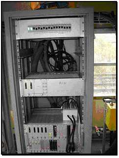
The EVC, the RIU and the power distribution module are installed in a cubicle by means of appropriate lateral guide that allow to easily remove the rack. Fig.3 shows, starting from the bottom to the top, the above-cited racks.
Fig.3 : The main cabinet
The power distribution module allow to powered all the ERTMS peripherals through circuit breakers in order to protect the electronic equipment.
The RIU allows to adapt the input/output towards the train devices. This module contains two 24V power supply module feeding the two electrovalves for the emergency brake and a relay contact, driven by the EVC, that commands the traction cut off.
The EVC receives the cab selection information directly from the train interface, while the selected direction information is given by the simulation box, because with this train is not possible to have such a kind of information at standstill.
In order to permit a full testing without interfere with the train movements, the emergency brake and traction cut off applications have been simulated through lamps in the simulation box.
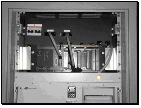
The four GSM-R mobile stations and the related two power supply modules are housed in a different cabinet, as shown in Fig.4.
Fig.4 : The GSM-R rack
The two GSM-R data modules are connected to the EVC, while just one of the two GSM-R voice modules is connected to a GSM-R telephone handset installed in the driving cab sideways of the DMI (see Fig.5). Both handset and DMI are mounted on a rotating mechanical support.
Fig.5 : The DMI and handset installation
External on-board installation
On ALe601, both the Eurobalise antennas are installed on the bogie respectively 2.40m and 6.86m far from the free buffers. The height from the top of the rails is 0.21m.
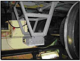
On the Le480, one Eurobalise antenna is installed on the bogie 2,36m far from the free buffers while the other one is mounted under the frame 6,62m far from the free buffers. The height from the top of the rails is 0.21m. Fig.6 shows the mechanical support designed for the antenna mounted under the frame.
Fig.6 : The Eurobalise antenna installation
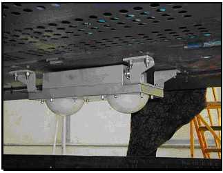
The two radar sensors are installed under the frame respectively 9m and 14,60m far from the free buffers with the same configuration on both locos (see Fig.7). The height from the top of the rails is 0.24m.
Fig.7 : Radar installation
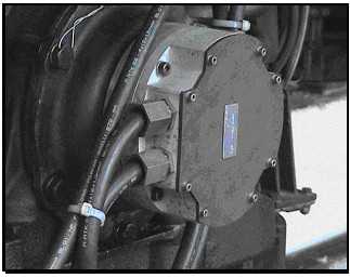
The two wheel sensors have to be installed on different axles. On Le480 they have been mounted on the same side while on ALe601 on both sides. In order to mount the wheel sensor a dragging shaft and a flange that realises the mechanical adaptation between the axle and the sensor are needed. Fig.8 shows wheel sensor installation.
Fig.8 : The wheel sensor installation
ALe601 and Le480 are equipped with four GSM-R antennas previously described installed on the roof, each of ones dedicated to one GSM-R mobile station installed. The distance between the antenna is equal to 1m.
Installation feedback
During the installation of the different peripherals and sensors, some problems have been encountered, such as:
- difficulty to right cabling the first Eurobalise antenna plug connector due to its differences with the connector normally used on the Italian rolling stock;
- necessity to dismount the radar sensor in order to adjust its position (tilting and pitching regulation) because of the regulation system adopted;
- difficulty to realise the supports in the cubicle for the rack’s housing.
It has to be take into account that some aspects could have a strong impact with regard to the further installation. In fact, one of the biggest problem is related to the availability of free space under the loco for the installation of two Eurobalise antennas and two radar sensors, that are duplicated for availability reasons, according to the required constraints. At present then, the wheel sensor doesn’t allow to interface the axial current return device that is more and more used on the Italian high speed trains.
Italian trial site description
The Italian trial site is about 60km long and runs from Firenze Campo di Marte station to Arezzo station on the DD line Bologna-Firenze-Roma, one of the busiest line in the Italian network. The maximum operational speed is 250km/h. Along the track there are a lot of tunnels and viaducts due to the fact that this line runs through the Appennini mountain chain.
The line is equipped with 134 balises groups, 112 of them are switchable and the others are fixed. Each switchable balises group is constituted of 2 balises, while just one balise is used for the fixed ones. Along the track 66 encoders are installed in order to drive the switchable balises.
16 mBBC (mini Balise Block Center) provides all the interlocking information to the RBC located in Firenze Campo di Marte station.
With regard to the radio aspects, the GSM-R radio coverage along this portion of the test track is provided by 14 BTS (Base Transceiver Station) and 13 handovers, two of them occurring in tunnels. In particular, an handover procedure occurs at the middle of San Donato tunnel (11km long) and the other in the tunnel of Castiglione Umbertini. All the BTS involved along the used portion of the track are controlled by one BSC (Base Station Controller) located in Arezzo and connected to the MSC (Mobile services Switching Centre) installed in Firenze S. Maria Novella station. The RBC is connected to the GSM-R network using two ISDN primary channels coming directly from the MSC.
The GSM-R network is configured with no authentication and no ciphering. All the data communication is performed using the transparent mode, without any error correction by the GSM-R network.
Starting from November the track-side equipment has been gradually configured in order to allow level 2 functional tests on site. The first tests runs involved 16Km of line from Arezzo to Valdarno Sud, allowing to perform level 2 functional tests just in one direction. The balises groups programmed were 15, just in the Arezzo-Firenze direction. The GSM-R radio coverage along this portion of the test track is provided by 5 BTS with 4 handovers, one of these very critical occurring inside the Castiglione Umbertini tunnel.
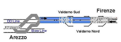
Since February 2001, the runs have been performed along 30km from Arezzo to Valdarno Nord (refer to Fig.9). The balises groups programmed were 58 allowing to perform level 2 functional tests on both directions. The GSM-R radio coverage along this portion of the test track is provided by 9 BTS and 8 handovers, one of these occurring in the Castiglione Umbertini tunnel.
Fig.9 : The ERTMS level 2 area
Functional scenarios description
During this first trails campaign some scenarios have been played in order to see the behaviour of the ERTMS system in a real railway environment. It has to be emphasised that even if not necessary in a level 2 area, the existing signals has been taken into account for logistic aspects.
Scenario 1: from Arezzo to Valdarno Sud
The train is brought, using the national signalling, from Arezzo station to the main signal protecting the entering in the DD line and stopped in front of it. A level 2 awakening is then carried out. After the data entry procedure performed by the driver, a communication session is opened with the RBC. After this, the driver has to select "start of mission". The RBC, not knowing the position of the train, gives a Staff Responsible (SR) Movement Authority (MA). The train can be moved.
After passing over the balises group located near the main signal, the train sends a "position report" to the RBC, which allows the RBC to know the train position and direction. As consequence, a Full Supervision (FS) MA is sent to the train.
The train equipment will take into account possible TSR (Temporary Speed Restriction) requirement contained in the MA. The DMI indication leads the driver to follow this speed requirement.
Along the trip, a section of route previously set is cancelled by the traffic operator in Firenze Campo di Marte. This causes the RBC to send a "Conditional Emergency Stop" message to the train. This message is displayed to the driver on the DMI, while the on-board receives the new MA restricted limit.
Due to the "Conditional Emergency Stop", the train is led to a standstill in front of the red signal (before the balises group associated to that signal).
The opening of the signal (turn to green) causes the RBC to revoke the Conditional Emergency Stop, sending a new FS MA up to Valdarno Sud. The driver has to follow the braking curve and stop the train within the end of the MA.
Scenario 2: from Arezzo to Firenze Campo di Marte
This scenario is similar to the previous one, with the exception that an automatic level 2 to level 0 transition is foreseen.
Before reaching the Level 2 boundary located in Valdarno Nord, the RBC sends a "Level 0 announced" message to the on-board equipment. A text message is also displayed to the driver on DMI. In proximity of the boundary, the driver has to acknowledge the level transition in order to avoid a train trip and consequent brakes application. The transition mode order is then given to the on-board equipment by the balises group delimiting the boundary.
Scenario 3: from Firenze campo di Marte to Arezzo
The train starts from Firenze Campo di Marte station with a level 0 awakening. The driver selects "level 0" during the data entry procedure and after this "start of mission". The "unfitted mode" transition has to be then acknowledged by the driver. The train can be moved. In unfitted mode, the on-board subsystem supervises a ceiling speed.
Before reaching Valdarno Nord, a balises group informs the on-board equipment of the incoming Level 2 area and gives it all the information necessary to establish a communication session with the RBC. The entry in the level 2 determines the automatic transition to the FS mode.
Also this scenario foresees TSR and Conditional Emergency Stop and related revocation.
An automatic level 2 to level 0 transition is realised exiting the DD line in order to reach Arezzo station.
Experimental results
The tests were performed both during the daily circulation and the night. The runs have been made at different speed. For the system integration tests (radio communication, odometer measurements, balises detection) were performed at a maximum speed of 160Km/h. The functional scenarios were played mainly at a maximum speed of 140Km/h.
Equipment’s compatibility aspects
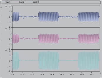
The first step of the tests was to check the compatibility between ERTMS and BACC system, in order to put in evidence eventually interferences caused by the ERTMS apparatus to the Italian signalling equipment.
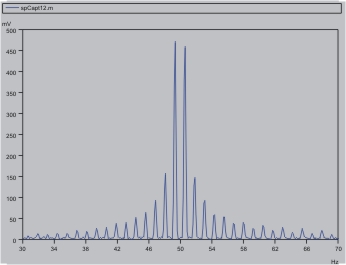
The compatibility test have been performed checking the BACC signals sensed on-board. Fig.10 and Fig.11 show, respectively in time and frequency dominion, the BACC signal with ERTMS equipment turned on. No incompatible signal was detected during all the test runs.
Fig.10 : BACC time dominion signal with ERTMS equipment turned on
Fig.11 : BACC frequency dominion signal with ERTMS equipment turned on
Radio aspects
The great part of the runs were performed connected the GSM-R mobile stations to the ERTMS system in order to test the overall system. Some runs were dedicated to test the radio performance connecting the GSM-R mobile stations directly to PC with special software able to simulate a real ERTMS communication.
The GSM-R network was configured with no authentication and no ciphering. All the data communication were performed using the transparent mode, so without any error correction by the GSM-R network.
GSM-R Antenna installation
Perhaps the short distance between the GSM-R antenna could not be enough to avoid interference in case of simultaneous communication using the same timeslot and adjacent carrier. No problem was detected during all the test runs due to this point.
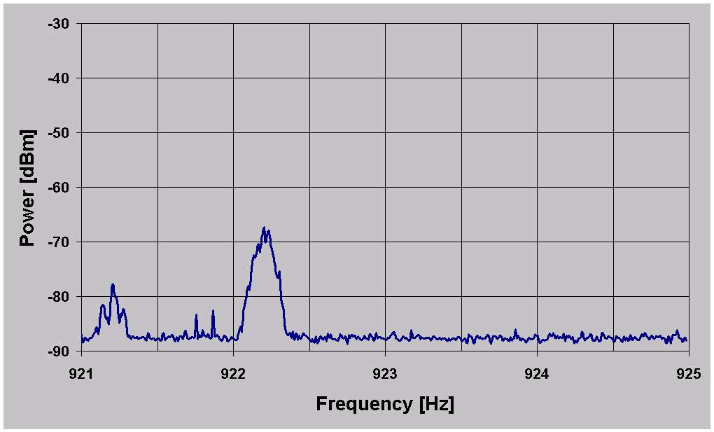
Coverage
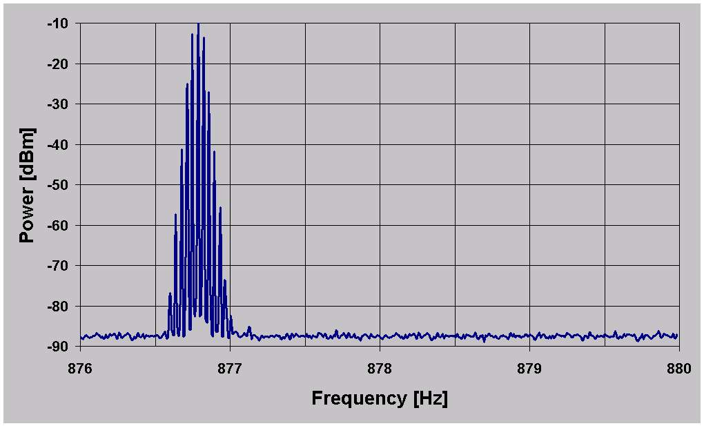
Along all the track the signal level (RxLev) was greater than -104dBm. No problem due to network coverage. The data was acquired using a test mobile operating in the GSM-R band and using the report generated directly by the GSM-R mobile station installed on borne. Fig.12 and Fig.13 show, respectively, a typical power spectrum of GSM-R DOWN and UP band acquired during a test.
Fig.12 : GSM-R DOWN band: Typical power spectrum
Fig.13 : GSM-R UP band: Typical power spectrum
End-to-end transmission delay
It was evaluated the end-to-end delay for an asynchronous transparent data connection (4800 and 9600bit/s). Two types of measurements have been performed: mobile-to-mobile call and mobile to fixed ISDN call. The measurement reports a mean delay value between 400 and 450ms in case of mobile-to-mobile communication and between 280 and 300ms in case of mobile to ISDN (taking into account that in this case some delay is introduced by the Access Server elaboration time).
Handover
The handover break, during which the channel is "virtually" closed, is about 400ms. It seems independently from the speed of the train and more related to the RxLevel value: less is the signal level, longer is the handover duration. This value was measured using the internal monitoring system of the GSM-R mobile station; from the user point of view it’s a little bit longer, but less than 600ms.
Data error rate
The measurement was made using the ERTMS data communication. The configuration was: mobile to fixed ISDN with the mobile caller (train) and the fixed ISDN called party (RBC).
The main sources of errors have been identified:
- Handover procedure temporary close the channel and induced error burst
- Noise or error bursts randomly induced
During the handover the communication channel is closed and all the bytes sent are lost. The impact is heavy for the application side that has to retransmit the lost bytes after some timer expiration. Due to the relative low transmission rate of ERTMS application in comparison with the channel bit rate, not in all handovers there is a lost of data (it depends if during the handover window some bytes are sent or not).
Sometimes some noisy bytes are induced and received by the end user.
Generally errors occur only during the handover.
Performance degradation due to radio coverage
It seems there is no appreciable impact of radio coverage in the data communication from the end-user (EVC or RBC in this case) point of view. Difference runs has been performed inserting 10 or 20dB of antenna attenuation in order to test the error transmission.
Performance degradation due to train speed
It seems there is no appreciable impact of train speed in the data communication from the end-user (EVC or RBC in this case) point of view.
Eurobalises detection aspects
Level detection
Due to a perturbation caused by a wrong grounding connection of the shield of the antenna cable, a permanent signal detection was diagnosed on-board but no telegrams decoding error was detected. The problem was solved rightly wiring the shield.
Balises detection
All the Eurobalises, programmed or not, along the track (from Firenze Campo di Marte to Arezzo) were detected by the on-board equipment.
Telegram decoding
A great number of runs were performed at different speeds and no telegram decoding errors occurred. All the Eurobalises rightly programmed have been decoded. The detection but not decoding of a programmed Eurobalise has been always due to a bad balise programming.
Further development
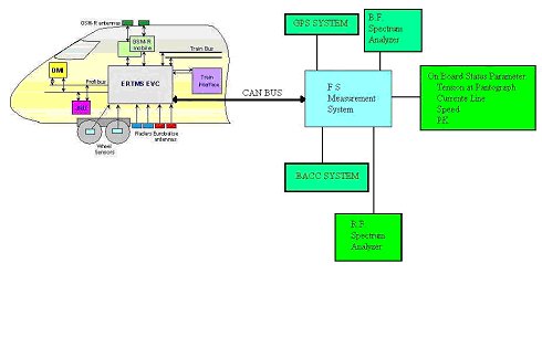
Evolution of the measurement system
Up to now the FS measurement system is completely separate from the EVC in order to allow the constructor to effect the preliminary test and debug of the ERTMS on-board system. This measurement system allows to:
- check the compatibility between ERTMS and BACC equipment;
- check the coverage of the GSM-R network.
- acquire the speed and pk signals through a link with the BACC equipment.
- acquire the speed and pk signals through a real-time DGPS system.
- acquire the signals of state of the machine such as:
- tension line at the pantograph;
- current absorbed;
- issue of harmonic components (only for the trains with electronic driving, always for the problems of compatibility above-cited).
Overcome the phase of debugging, it is necessary to verify the functionality of the system in terms of:
- parameters elaborated by the EVC in the different configurations;
- parameters that intervene in the process of management of the information;
- degraded conditions;
- simulation of all the possible potential dangerous situations under which the system could be operate.
For this, it is necessary to directly interact with the EVC. Fig.4 shows the scheme of the FS measurement system that it will be implemented.
Fig.14 : The incoming FS measurement system
Other locos to be equipped
The next tests will be performed on the followings machine:
- ETR500P
- E402B
- E412
Conclusion
The results obtained during this first phase of debugging of the ERTMS system don't allow us to effect precise evaluations on the characteristic parameters of the system itself. We can however affirm that, from a functional point of view, good results have been reached.
More precise information in terms of performance, reliability and safety will be obtained from the further tests starting at the end of 2001and involving both the Ale601-Le480 and the other trains.